Child pages:
The Laboratory of Plasma Physics(LPP) is in charge of providing the Low Frequency Receiver(LFR) as a part of the Radio & Plasma Waves(RPW) instrument which will be embedded in Solar Orbiter probe. Solar Orbiter launch window is set to October 2018.
The LFR instrument is designed to produce and transmit waveforms (WF), averaged spectral matrices (ASM) and basic parameters (BP) from LF electromagnetic data (quasi DC-10kHz). The electric field data are provided by the electric antennas (ANT) and by the entity that controls their operation (BIAS). The magnetic field data are coming from the searchcoil magnetometer (SCM).
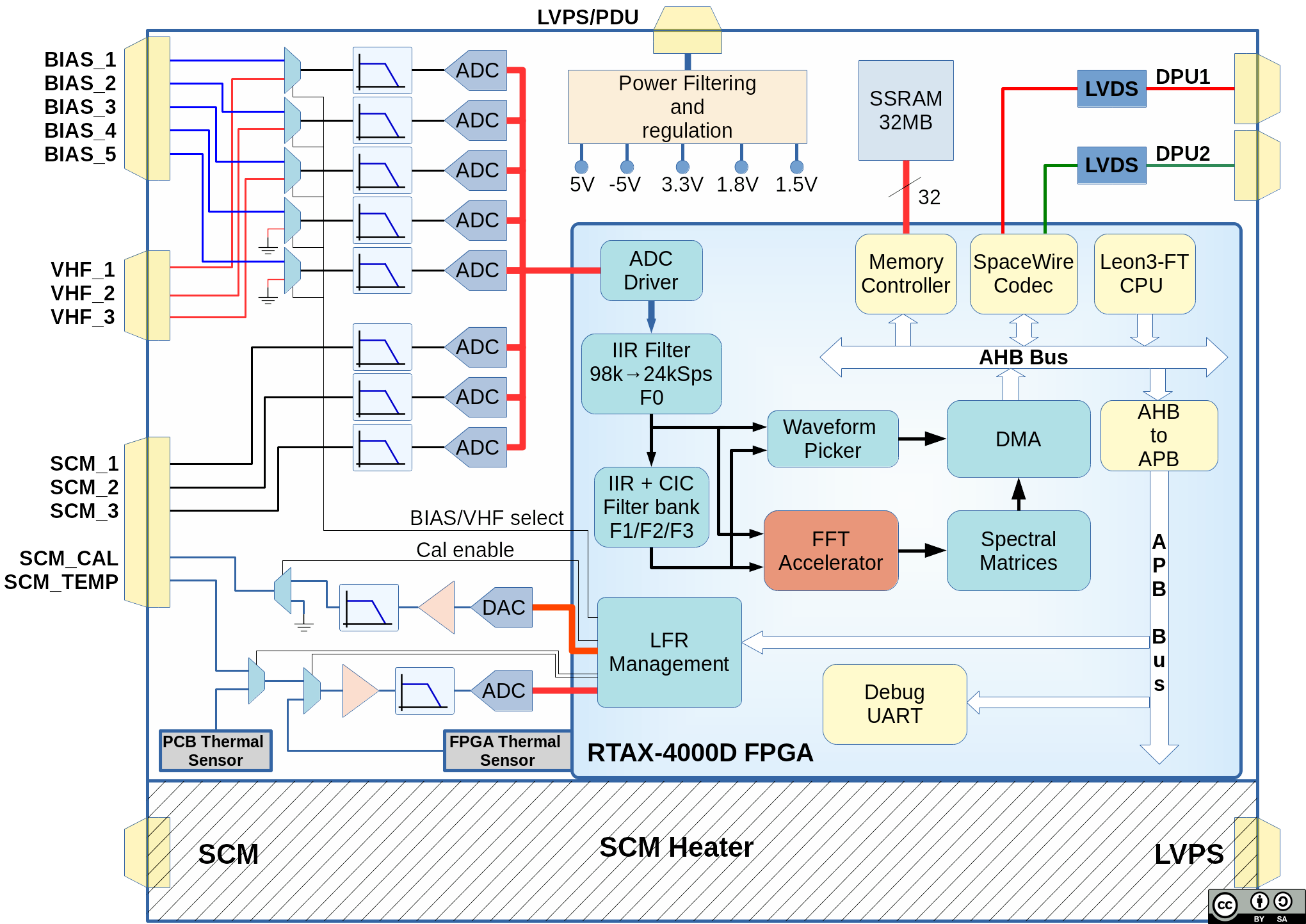
The LFR board will also have a special area reserved to the SCM Heater circuitry. LFR will monitor its own temperature and the temperature of the SCM. It will generate a calibration signal for the SCM.
The science objective of LFR is the study of the electromagnetic wave activity in the extended corona and the solar wind, from a fraction of a Hertz to about 10 kHz, which should cover the electron gyrofrequency and most of the Doppler-shifted frequencies of the low frequency plasma waves. The main waves to be observed in this frequency range are thus kinetic or inertial Alfven waves, ion cyclotron waves, ion acoustic waves, and magnetosonic or whistler mode waves. Their characterization and the determination of their respective role in heating and accelerating the solar wind during its expansion is the main scientific issue addressed by LFR. Another important subject for LFR is the study of the low frequency plasma waves associated to solar wind disturbances, as for instance interplanetary shocks.
Characterizing the low frequency waves in the solar wind involves the capability of the LFR to distinguish solitary waves from broadband wave activity, to cover turbulence and plasma instabilities, to identify the wave modes at work. Performing a multi-component analysis of the data is thus mandatory, using either a classical Fourier analysis or another treatment of the waveforms more appropriate to turbulence analysis.
Given the limitations in the telemetry, it is necessary to implement specific techniques to take the maximum advantage of the data. The LFR is tailored to optimize the scientific return of the data. The LFR design gives the possibility of mixing different types of output data, from low-level processed data (waveform data) to high-level processed data (averaged spectral matrices and their derived parameters), with various data rate possibilities (continuous or cyclic transmission, adaptable frequency bandwidth as well as adaptable frequency and time resolutions). The scientific added value stems from the choice of the most relevant combination of the different data to be transmitted, according to the RPW Science Requirements Document (RD3). A number of predefined working modes will be defined, but it will also be possible to define other working modes in flight.
LFR will digitize 8 signals among these 11 signals. The routing strategy is based on two main configurations named BIAS_WORKS and BIAS_FAILS. Whatever the configuration, the three channels coming from SCM are digitized.
The LFR analog part implements:The digital part implements:

LESIA's RPW website
CNES's RPW page
RPW, LESIA
Search Coil Magnetometer(SCM), LPCEE
Time Domain Sampler(TDS), IAP
BIAS, IRF
Digital Processing Unit(RPW-DPU), IWF
Thermal Noise Receiver & High Frequency Receiver(TNR-HFR), LESIA
RPW-DPU onboard Software, LESIA