Wiki » History » Revision 16
« Previous |
Revision 16/20
(diff)
| Next »
Malik Mansour, 02/02/2015 07:48 PM
ICI4 mission purpose
- Table of contents
- ICI4 mission purpose
- ICI4 instrumental payload
- The launcher & The rocket range
- LPP contribution
The main objective is to reveal the controlling mechanism(s) of plasma instabilities that generates HF radar backscatter targets/GPS scintillations in the F-region polar cap ionosphere. Plasma irregularities may occur in association with several classes of events such as Flow Channel Events (FCEs) and Reversed Flow Events (FTEs), auroral arcs, and polar cap patches. The main mission objective is to carry out in-situ measurements to provide information about the underlying physics of space weather phenomena in the polar cap ionosphere. The main objective is to reveal the controlling mechanism(s) of plasma instabilities that generates HF radar backscatter targets/GPS scintillations in the F-region polar cap ionosphere. Plasma irregularities may occur in association with several classes of events such as Flow Channel Events (FCEs) and Reversed Flow Events (FTEs), auroral arcs, and polar cap patches. The main mission objective is to carry out in-situ measurements to provide information about the underlying physics of space weather phenomena in the polar cap ionosphere.
ICI4 instrumental payload
The instrumental payload is the result of an international collaboration involving 4 differents countries. For this 4th edition, the ICI payload is made up of height instruments. Six of them are used for measuring the plasma characteristics and the two last ones are used for monitoring the rocket attitude and trajectory. The six scientific instruments aim to mesure the electromagnetic waves as well as the particules behavior of the ionospheric plasma. Thus several magnetometers and electric antenna as well as a Low Energy Particle spectrometer are used simultaneously during the flight.
 |
 |
 |
 |
- Fixed Bias Langmuir Probe (FBP) – ISAS/JAXA.
- Low Energy Particle spectrometer (LEP) – ISAS/JAXA.
- Multi Needle Langmuir Probe (mNLP) – University of Oslo.
- Digital Sun Sensors (DSS) – University of Oslo.
- Sounding Rocket Attitude Detection System (SRADS2) – University of Oslo.
- Electric Field Instrument (E-field) – University of Oslo.
- AC/DC Magnetom. (SwiMM) – LPP, France
- Flux Gate Magnetometer (FGM) – University of Alberta, Canada
Fixed Bias Langmuir probe (FBP,from ISAS/JAXA)
The main objective of this instrument is to monitor the small-scale perturbation of the electron density along the rocket trajectory. Such a density perturbation is thought to reflect various meso-or micro-scale phenomena such as the plasma irregularity, instability, and wave-particle interaction. The measured density variation will be compared with other parameters simultaneously obtained from other instruments on the rocket. A spherical probe with a diameter of 2 cm is adopted as a detector for the electron density measurement, and is put on the top of payload zone of the rocket. In ICI-4, two circular probes with a diameter of 2 cm are additionally adopted to monitor the local ion density. A surface of the probe is coated with gold. The electron and ion probes are biased with a positive voltage of +4 V and a negative voltage of -3 V, respectively, with respect to the rocket potential. The electron and ion currents incident to the probe are amplified and subsequently transferred to the telemetry system. Two levels of DC current gain are prepared so that the probe can measure in a wide range of the plasma density.
Low Energy Particle experiment (LEP,from ISAS/JAXA)
LEP consists of two sensors ESA and ISA. ESA measures the electron distribution function in the energy range between 10eV and 10keV while ISA measures the ion distribution function in the energy
range between 10eV/q and 10keV/q. The ESA and ISA sensors are top-hat type electrostatic analyzers with a pair of flat disks that works as a collimator at the entrance and toroidal electrodes inside. The inner toroidal electrode is supplied with high voltage swept between 0V and +3kV (ESA)/-3kV (ISA). The electrons/ions coming through the collimator are attracted down toward the inner electrode by the action of the applied potential. Only the electrons/ions with specific energy range can further travel down to the exit of the electrodes. The electrons/ions passing through the electrode enter to Micro-Channel Plate (MCP) and are intensified to detectable charge pulses. Finally, the charge pulses are received by annular discrete anodes that are divided into 16 parts. The positions where the charge pulses are detected correspond to the incident azimuthal directions of the elect
Multi-Needle & Sphere Langmuir Probe (from UIO)
The experiment consists of a combination of in total eight miniaturized cylindrical and spherical Langmuir probes. The probes are mounted between the knee-joints on the E-field booms and the E-field probe, close to the knee-joints. The probes have a total length of ~50 mm. The cylindrical and spherical probes are biased at individual potentials, and sampled simultaneously. The electron density is calculated using the linear relationship between the bias of the probes and the square of the current collected by the cylindrical probes. The electronics consists of an eight-channel data acquisition unit populating three units in the UiO instrument stack.
Electric Field and Wave Experiment (E-field,from (UIO))
Four 45 mm diameter E-field probes are used to measure 3D E-field in both AC and DC components. The probes are mounted on the tips of the four front booms. The instrument consists of two differential channels measuring the field between two opposite mounted probes in addition to four channels with single ended measurements of all four probes relative to the payload. This instrument has a new electronics, based on the version used on earlier ICI-flights. The pre-amplifiers are removed and the earlier separate AC- and DC channels are now combined in one covering the whole bandwidth from DC to ~8.6 kHz. The electronics is populating two units in the UiO instrument stack.
The launcher & The rocket range
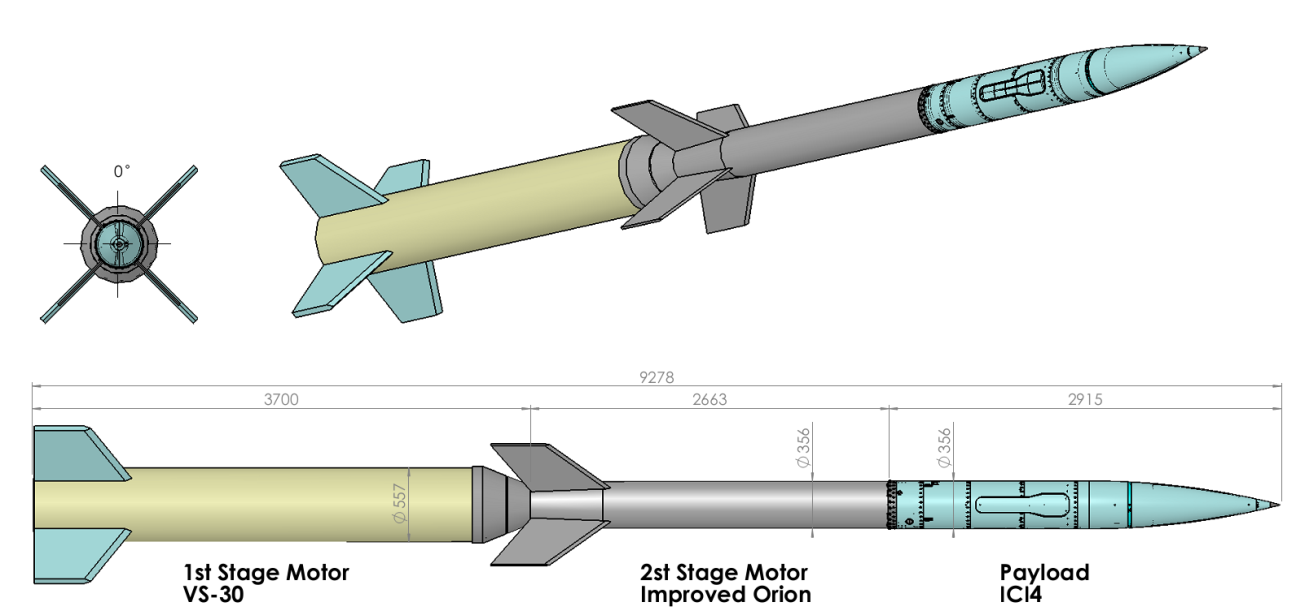
The ICI-4 is a two stage, unguided and fin stabilized vehicle carrying a 356 mm diameter, 2915mm long and 135,9 kg payload to an altitude of about 356 km. The motor stages are connected by an interstage adapter and separated by drag forces at first stage burnout at 26 seconds, while the second stage motor and the payload are connected by an adapter section (manacle joint) without any separation system. Each motor has 4 fins which impart a roll rate which will spin the vehicle to reduce dispersion in vase of trust misalignment and achieve flight stability throughout the gyroscopic effect. Second stage motor ignition is initiated at 32.5 seconds after lift-off by an onboard system (Second Stage Ignition Unit) delivered by DLR.
 |
 |
The rocket had been launch from the Andoya Rocket Range (Norway). In order to monitor the trajectory in real time, the Trajectory and Position System (TPS) has been used. This system utilizes all available tracking information from telemetry antennas, as well as slant range based on measurements of the Doppler displacement in the telemetry signal. The launch windows was between the 17 and the 22 of February 2015. Detailed diagnostics of launch conditions have been be provided by the CUTLASS HF radar,EISCAT Svalbard Radar (ESR) and two all-sky imagers respectively located at the Kjell Henriksen Observatory (KHO) and at the Johan Sverdrup Station (Ny-Ålesund, Spitzberg). In addition solar wind data from ACE have been used to allow short-term auroral forecasts.
The requested condition ti trigger the launch was:
- The detection of an HF radar backscatter/GPS scintillation associated with either: Flow Channel Events (FCEs) and Reversed Flow Events (FTEs)
- The presence of an auroral arcs observed optically, and polar cap patches observable by both radar and optical techniques.
 |
 |
LPP contribution
Sensor for Wideband Magnetic Field Measurement (SwiMM)
Induction magnetometer (SCM)
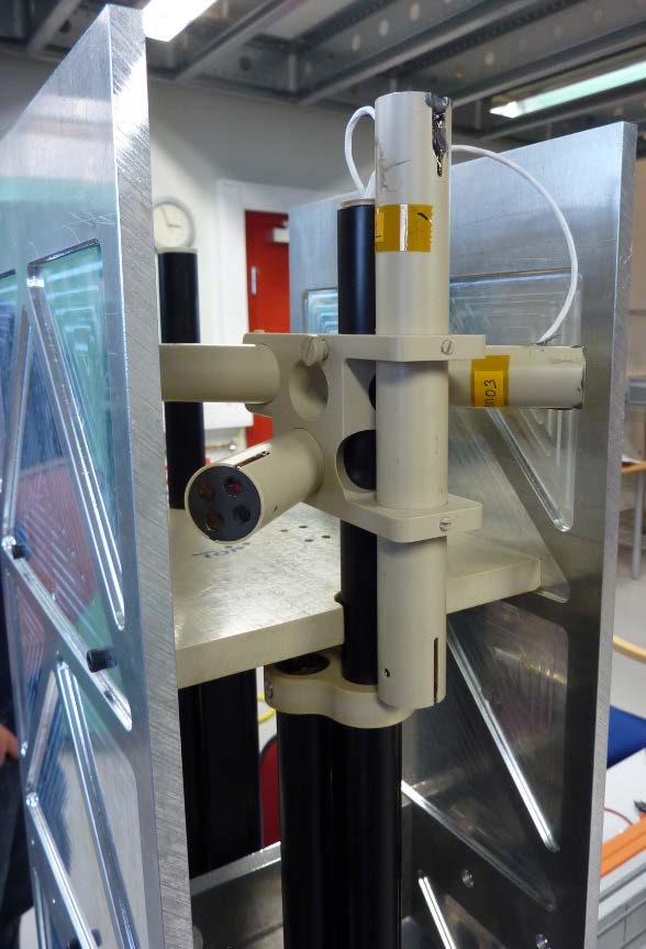
It will consist in three perpendicular search-coil antennas with mounting hardware, to measure the X, Y and Z-components of the magnetic field. The magnetic antenna has measure the magnetic field components of magnetic waves from a few Hz to ~20 kHz with high sensitivity. AC Searchoil Magnetometer (SCM-LPP). LPP has a long heritage in search coil magnetometer (SCM) design, dedicated to AC magnetic field measurement, and is involved in many space physics missions (ESA, NASA, CNES & JAXA): GEOS, Cluster, Themis, BepiColombo, MMS. SCM consist in a high turn number primary coil wounded on a ferromagnetic core and a secondary coil used to flat the sensor transfert function.. The full experiment is based on the SCM-AC pack provided for ICI-4 rocket experiment including AC sensors, pre-amplifier, and DC/DC converter. Optionally an on-board signal processing (including: anti-aliasing filtering, CAD and a FPGA including FFT computation and scientific phenomenon triggering) and a DC system measurement could be provided. SCM will allow measurement of weak magnetic fluctuations associated with plasma waves in the frequency range from 1Hz to 4 kHz, with a sensitivity of 100pT/√Hz at 1Hz, 2pT/√Hz at 10 Hz, 0.02pT/√Hz at 1 kHz. The ADM sensor will be mounted on the aft section boom system to reduce radiated magnetic field noise from the rocket.
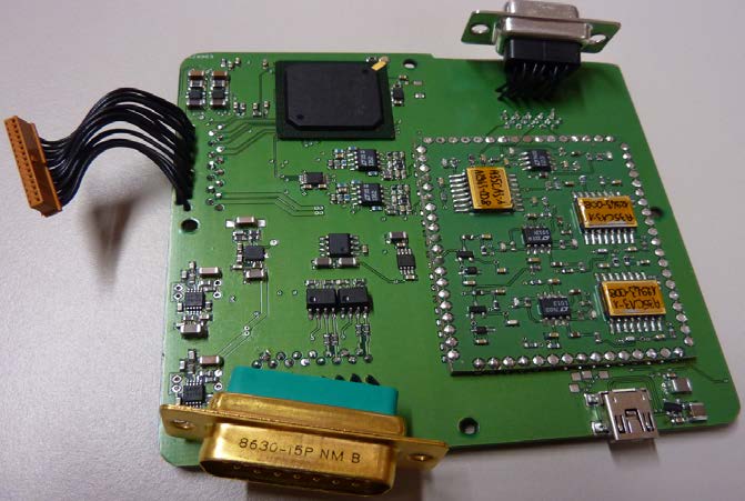
Main Electronic Box
This box contains all the electronic functions to amplify search coil antenna signal, measure continuous magnetic field, convert and filter this signals and transfer them to rocket telemetry system. To measure DC magnetic field we use four three axis commercial magneto-resistances (AMR) spaced by 8cm, sampled with 24bits resolution. Inherent limitation from AMR sensors are reduced by using set/reset technic and some algorithms,. The shearc-coil amplifier is based on ASIC technology to ensure a good resolution and bandwidth without increasing too much the power consumption. This box contains all the electronic functions to amplify search coil antenna signal, measure continuous magnetic field, convert and filter this signals and transfer them to rocket telemetry system. To measure DC magnetic field we use four three axis commercial magneto-resistances (AMR) spaced by 8cm, sampled with 24bits resolution. Inherent limitation from AMR sensors are reduced by using set/re set technic and some algorithms,. The shearc-coil amplifier is based on ASIC technology to ensure a good resolution and bandwidth without increasing too much the power consumption.This box contains all the electronic functions to amplify search coil antenna signal, measure continuous magnetic field, convert and filter this signals and transfer them to rocket telemetry system. To measure DC magnetic field we use four three axis commercial magneto-resistances (AMR) spaced by 8cm, sampled with 24bits resolution. Inherent limitation from AMR sensors are reduced by using set/reset technic and some algorithms,. The shearc-coil amplifier is based on ASIC technology to ensure a good resolution and bandwidth without increasing too much the power consumption. This box contains all the electronic functions to amplify search coil antenna signal, measure continuous magnetic field, convert and filter this signals and transfer them to rocket telemetry system. To measure DC magnetic field we use four three axis commercial magneto-resistances (AMR) spaced by 8cm, sampled with 24bits resolution. Inherent limitation from AMR sensors are reduced by using set/reset technic and some algorithms,. The shearc-coil amplifier is based on ASIC technology to ensure a good resolution and bandwidth without increasing too much the power consumption.
 |
|
This box contains all the electronic functions to amplify search coil antenna signal, measure continuous magnetic field, convert and filter this signals and transfer them to rocket telemetry system. To measure DC magnetic field we use four three axis commercial magneto-resistances (AMR) spaced by 8cm, sampled with 24bits resolution. Inherent limitation from AMR sensors are reduced by using set/reset technic and some algorithms,. The shearc-coil amplifier is based on ASIC technology to ensure a good resolution and bandwidth without increasing too much the power consumption.This box contains all the electronic functions to amplify search coil antenna signal, measure continuous magnetic field, convert and filter this signals and transfer them to rocket telemetry system. To measure DC magnetic field we use four three axis commercial magneto-resistances (AMR) spaced by 8cm, sampled with 24bits resolution. Inherent limitation from AMR sensors are reduced by using set/reset technic and some algorithms,. The shearc-coil amplifier is based on ASIC technology to ensure a good resolution and bandwidth without increasing too much the power consumption.This box contains all the electronic functions to amplify search coil antenna signal, measure continuous magnetic field, convert and filter this signals and transfer them to rocket telemetry system. To measure DC magnetic field we use four three axis commercial magneto-resistances (AMR) spaced by 8cm, sampled with 24bits resolution. Inherent limitation from AMR sensors are reduced by using set/reset technic and some algorithms,. The shearc-coil amplifier is based on ASIC technology to ensure a good resolution and bandwidth without increasing too much the power consumption.This box contains all the electronic functions to amplify search coil antenna signal, measure continuous magnetic field, convert and filter this signals and transfer them to rocket telemetry system. To measure DC magnetic field we use four three axis commercial magneto-resistances (AMR) spaced by 8cm, sampled with 24bits resolution. Inherent limitation from AMR sensors are reduced by using set/reset technic and some algorithms,. The shearc-coil amplifier is based on ASIC technology to ensure a good resolution and bandwidth without increasing too much the power consumption.
DC Gradiometer
This box contains all the electronic functions to amplify search coil antenna signal, measure continuous magnetic field, convert and filter this signals and transfer them to rocket telemetry system. To measure DC magnetic field we use four three axis commercial magneto-resistances (AMR) spaced by 8cm, sampled with 24bits resolution. Inherent limitation from AMR sensors are reduced by using set/reset technic and some algorithms,. The shearc-coil amplifier is based on ASIC technology to ensure a good resolution and bandwidth without increasing too much the power consumption. This box contains all the electronic functions to amplify search coil antenna signal, measure continuous magnetic field, convert and filter this signals and transfer them to rocket telemetry system. To measure DC magnetic field we use four three axis commercial magneto-resistances (AMR) spaced by 8cm, sampled with 24bits resolution. Inherent limitation from AMR sensors are reduced by using set/reset technic and some algorithms,. The shearc-coil amplifier is based on ASIC technology to ensure a good resolution and bandwidth without increasing too much the power consumption. This box contains all the electronic functions to amplify search coil antenna signal, measure continuous magnetic field, convert and filter this signals and transfer them to rocket telemetry system. To measure DC magnetic field we use four three axis commercial magneto-resistances (AMR) spaced by 8cm, sampled with 24bits resolution. Inherent limitation from AMR sensors are reduced by using set/reset technic and some algorithms,. The shearc-coil amplifier is based on ASIC technology to ensure a good resolution and bandwidth without increasing too much the power consumption.
|
|
|
Performances & Technical characteristics
 |
|
Updated by Malik Mansour almost 10 years ago · 16 revisions