Wiki » History » Revision 12
« Previous |
Revision 12/20
(diff)
| Next »
Malik Mansour, 01/02/2015 12:30 AM
La mission ICI4
- Table of contents
- La mission ICI4
- La charge utile de la mission ICI4
- Objectifs scientifiques
- Le Lanceur et le site de Lancement
- La contribution du LPP
- La charge utile de la mission ICI4
The main objective is to reveal the controlling mechanism(s) of plasma instabilities that generates HF radar backscatter targets/GPS scintillations in the F-region polar cap ionosphere. Plasma irregularities may occur in association with several classes of events such as Flow Channel Events (FCEs) and Reversed Flow Events (FTEs), auroral arcs, and polar cap patches. The main mission objective is to carry out in-situ measurements to provide information about the underlying physics of space weather phenomena in the polar cap ionosphere. The main objective is to reveal the controlling mechanism(s) of plasma instabilities that generates HF radar backscatter targets/GPS scintillations in the F-region polar cap ionosphere. Plasma irregularities may occur in association with several classes of events such as Flow Channel Events (FCEs) and Reversed Flow Events (FTEs), auroral arcs, and polar cap patches. The main mission objective is to carry out in-situ measurements to provide information about the underlying physics of space weather phenomena in the polar cap ionosphere.
La charge utile de la mission ICI4
 |
 |
 |
 |
- Fixed Bias Langmuir Probe (FBP) – ISAS/JAXA.
- Low Energy Particle spectrometer (LEP) – ISAS/JAXA.
- Multi Needle Langmuir Probe (mNLP) – University of Oslo.
- Digital Sun Sensors (DSS) – University of Oslo.
- Sounding Rocket Attitude Detection System (SRADS2) – University of Oslo.
- Electric Field Instrument (E-field) – University of Oslo.
- AC/DC Magnetom. (SwiMM) – LPP, France
- Flux Gate Magnetometer (FGM) – University of Alberta, Canada
Objectifs scientifiques
The main objective is to reveal the controlling mechanism(s) of plasma instabilities that generates HF radar backscatter targets/GPS scintillations in the F-region polar cap ionosphere. Plasma irregularities may occur in association with several classes of events such as Flow Channel Events (FCEs) and Reversed Flow Events (FTEs), auroral arcs, and polar cap patches. The main mission objective is to carry out in-situ measurements to provide information about the underlying physics of space weather phenomena in the polar cap ionosphere. The main objective is to reveal the controlling mechanism(s) of plasma instabilities that generates HF radar backscatter targets/GPS scintillations in the F-region polar cap ionosphere. Plasma irregularities may occur in association with several classes of events such as Flow Channel Events (FCEs) and Reversed Flow Events (FTEs), auroral arcs, and polar cap patches. The main mission objective is to carry out in-situ measurements to provide information about the underlying physics of space weather phenomena in the polar cap ionosphere.
Le Lanceur et le site de Lancement
The main objective is to reveal the controlling mechanism(s) of plasma instabilities that generates HF radar backscatter targets/GPS scintillations in the F-region polar cap ionosphere. Plasma irregularities may occur in association with several classes of events such as Flow Channel Events (FCEs) and Reversed Flow Events (FTEs), auroral arcs, and polar cap patches. The main mission objective is to carry out in-situ measurements to provide information about the underlying physics of space weather phenomena in the polar cap ionosphere. The main objective is to reveal the controlling mechanism(s) of plasma instabilities that generates HF radar backscatter targets/GPS scintillations in the F-region polar cap ionosphere. Plasma irregularities may occur in association with several classes of events such as Flow Channel Events (FCEs) and Reversed Flow Events (FTEs), auroral arcs, and polar cap patches. The main mission objective is to carry out in-situ measurements to provide information about the underlying physics of space weather phenomena in the polar cap ionosphere. The main objective is to reveal the controlling mechanism(s) of plasma instabilities that generates HF radar backscatter targets/GPS scintillations in the F-region polar cap ionosphere. Plasma irregularities may occur in association with several classes of events such as Flow Channel Events (FCEs) and Reversed Flow Events (FTEs), auroral arcs, and polar cap patches. The main mission objective is to carry out in-situ measurements to provide information about the underlying physics of space weather phenomena in the polar cap ionosphere.
 |
 |
The main objective is to reveal the controlling mechanism(s) of plasma instabilities that generates HF radar backscatter targets/GPS scintillations in the F-region polar cap ionosphere. Plasma irregularities may occur in association with several classes of events such as Flow Channel Events (FCEs) and Reversed Flow Events (FTEs), auroral arcs, and polar cap patches. The main mission objective is to carry out in-situ measurements to provide information about the underlying physics of space weather phenomena in the polar cap ionosphere.
La contribution du LPP
Le magnetometre à induction SCM
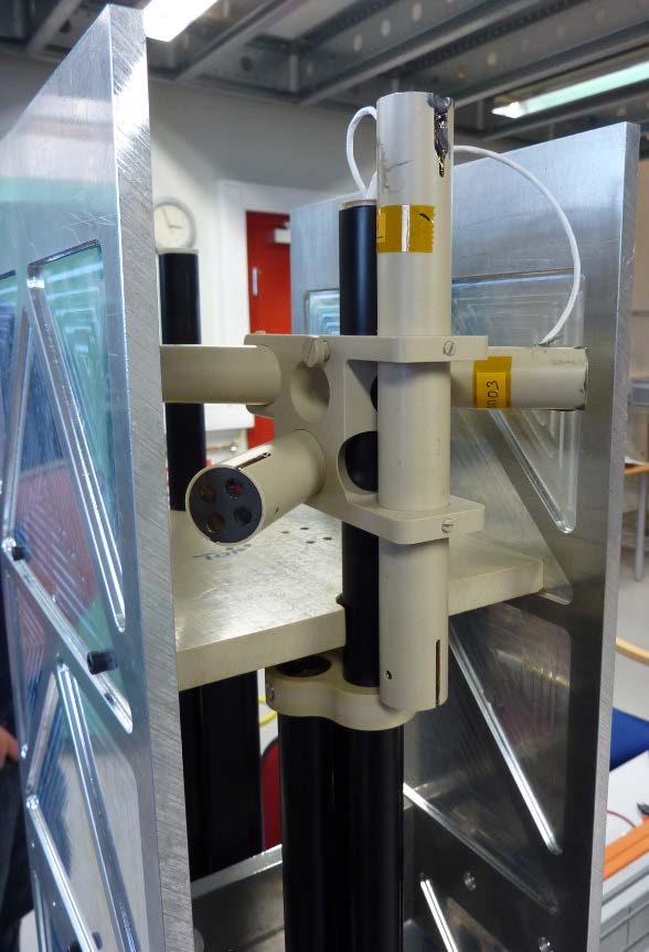
It will consist in three perpendicular search-coil antennas with mounting hardware, to measure the X, Y and Z-components of the magnetic field. The magnetic antenna has measure the magnetic field components of magnetic waves from a few Hz to ~20 kHz with high sensitivity. AC Searchoil Magnetometer (SCM-LPP). LPP has a long heritage in search coil magnetometer (SCM) design, dedicated to AC magnetic field measurement, and is involved in many space physics missions (ESA, NASA, CNES & JAXA): GEOS, Cluster, Themis, BepiColombo, MMS. SCM consist in a high turn number primary coil wounded on a ferromagnetic core and a secondary coil used to flat the sensor transfert function.. The full experiment is based on the SCM-AC pack provided for ICI-4 rocket experiment including AC sensors, pre-amplifier, and DC/DC converter. Optionally an on-board signal processing (including: anti-aliasing filtering, CAD and a FPGA including FFT computation and scientific phenomenon triggering) and a DC system measurement could be provided. SCM will allow measurement of weak magnetic fluctuations associated with plasma waves in the frequency range from 1Hz to 4 kHz, with a sensitivity of 100pT/√Hz at 1Hz, 2pT/√Hz at 10 Hz, 0.02pT/√Hz at 1 kHz. The ADM sensor will be mounted on the aft section boom system to reduce radiated magnetic field noise from the rocket.
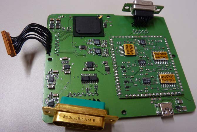
Main Electronic Box
This box contains all the electronic functions to amplify search coil antenna signal, measure continuous magnetic field, convert and filter this signals and transfer them to rocket telemetry system. To measure DC magnetic field we use four three axis commercial magneto-resistances (AMR) spaced by 8cm, sampled with 24bits resolution. Inherent limitation from AMR sensors are reduced by using set/reset technic and some algorithms,. The shearc-coil amplifier is based on ASIC technology to ensure a good resolution and bandwidth without increasing too much the power consumption. This box contains all the electronic functions to amplify search coil antenna signal, measure continuous magnetic field, convert and filter this signals and transfer them to rocket telemetry system. To measure DC magnetic field we use four three axis commercial magneto-resistances (AMR) spaced by 8cm, sampled with 24bits resolution. Inherent limitation from AMR sensors are reduced by using set/re set technic and some algorithms,. The shearc-coil amplifier is based on ASIC technology to ensure a good resolution and bandwidth without increasing too much the power consumption.This box contains all the electronic functions to amplify search coil antenna signal, measure continuous magnetic field, convert and filter this signals and transfer them to rocket telemetry system. To measure DC magnetic field we use four three axis commercial magneto-resistances (AMR) spaced by 8cm, sampled with 24bits resolution. Inherent limitation from AMR sensors are reduced by using set/reset technic and some algorithms,. The shearc-coil amplifier is based on ASIC technology to ensure a good resolution and bandwidth without increasing too much the power consumption. This box contains all the electronic functions to amplify search coil antenna signal, measure continuous magnetic field, convert and filter this signals and transfer them to rocket telemetry system. To measure DC magnetic field we use four three axis commercial magneto-resistances (AMR) spaced by 8cm, sampled with 24bits resolution. Inherent limitation from AMR sensors are reduced by using set/reset technic and some algorithms,. The shearc-coil amplifier is based on ASIC technology to ensure a good resolution and bandwidth without increasing too much the power consumption.
 |
|
This box contains all the electronic functions to amplify search coil antenna signal, measure continuous magnetic field, convert and filter this signals and transfer them to rocket telemetry system. To measure DC magnetic field we use four three axis commercial magneto-resistances (AMR) spaced by 8cm, sampled with 24bits resolution. Inherent limitation from AMR sensors are reduced by using set/reset technic and some algorithms,. The shearc-coil amplifier is based on ASIC technology to ensure a good resolution and bandwidth without increasing too much the power consumption.This box contains all the electronic functions to amplify search coil antenna signal, measure continuous magnetic field, convert and filter this signals and transfer them to rocket telemetry system. To measure DC magnetic field we use four three axis commercial magneto-resistances (AMR) spaced by 8cm, sampled with 24bits resolution. Inherent limitation from AMR sensors are reduced by using set/reset technic and some algorithms,. The shearc-coil amplifier is based on ASIC technology to ensure a good resolution and bandwidth without increasing too much the power consumption.This box contains all the electronic functions to amplify search coil antenna signal, measure continuous magnetic field, convert and filter this signals and transfer them to rocket telemetry system. To measure DC magnetic field we use four three axis commercial magneto-resistances (AMR) spaced by 8cm, sampled with 24bits resolution. Inherent limitation from AMR sensors are reduced by using set/reset technic and some algorithms,. The shearc-coil amplifier is based on ASIC technology to ensure a good resolution and bandwidth without increasing too much the power consumption.This box contains all the electronic functions to amplify search coil antenna signal, measure continuous magnetic field, convert and filter this signals and transfer them to rocket telemetry system. To measure DC magnetic field we use four three axis commercial magneto-resistances (AMR) spaced by 8cm, sampled with 24bits resolution. Inherent limitation from AMR sensors are reduced by using set/reset technic and some algorithms,. The shearc-coil amplifier is based on ASIC technology to ensure a good resolution and bandwidth without increasing too much the power consumption.
DC Gradiometer
This box contains all the electronic functions to amplify search coil antenna signal, measure continuous magnetic field, convert and filter this signals and transfer them to rocket telemetry system. To measure DC magnetic field we use four three axis commercial magneto-resistances (AMR) spaced by 8cm, sampled with 24bits resolution. Inherent limitation from AMR sensors are reduced by using set/reset technic and some algorithms,. The shearc-coil amplifier is based on ASIC technology to ensure a good resolution and bandwidth without increasing too much the power consumption. This box contains all the electronic functions to amplify search coil antenna signal, measure continuous magnetic field, convert and filter this signals and transfer them to rocket telemetry system. To measure DC magnetic field we use four three axis commercial magneto-resistances (AMR) spaced by 8cm, sampled with 24bits resolution. Inherent limitation from AMR sensors are reduced by using set/reset technic and some algorithms,. The shearc-coil amplifier is based on ASIC technology to ensure a good resolution and bandwidth without increasing too much the power consumption. This box contains all the electronic functions to amplify search coil antenna signal, measure continuous magnetic field, convert and filter this signals and transfer them to rocket telemetry system. To measure DC magnetic field we use four three axis commercial magneto-resistances (AMR) spaced by 8cm, sampled with 24bits resolution. Inherent limitation from AMR sensors are reduced by using set/reset technic and some algorithms,. The shearc-coil amplifier is based on ASIC technology to ensure a good resolution and bandwidth without increasing too much the power consumption.
|
|
|
La charge utile de la mission ICI4
 |
|
Updated by Malik Mansour almost 10 years ago · 12 revisions